I. Features:
The block is responsible for controlling pseudo control column and pedal force servo motor in Su-30 emulator. The servo motor makes pilots feel the force as real one in the different airspeeds and flight levels. Simultanously, the block collects position data of control column and pedal then sends them to the central computer AC1.
II. Principles:
The AC-1 (the central computer which controls all parts of emulator) passes information of pseudo force to the block via usb comunication standard. The block then calculates and send control signals to amplifier, in turn the amplifier control servo motor to create the neccesary pseudo forces for control column (pitch and roll channel) and pedal (yaw channel). At the same time, the block gets column and pedal position and send back to the AC-1.
III. Specifications
3.1. Fundamental specifications
| No | Nomenclatures | Units | Values |
| 1 | Supply voltage
– 24V DC – (+12)V DC; – (-12)V DC; – (+5)V DC. |
V V V V |
24±5% 12±5% -12±5% 5±5% |
| 2 | Power consumtion | W | <40 |
| 3 | Operating environment
– Temperature – Humidity |
0C % |
10÷30 < 80 |
| 4 | Storage environment
– Temperature – Humidity |
0C % |
15÷35 < 80 |
| 5 | Continuous ơperating | h | 4 |
| 6 | Life of expectancy | yr | 5 |
| 7 | Dimension (depth x width x height) | mm | 216 x 173 x 46 (±5mm) |
| 8 | Weight | kg | <2,5 |
| 9 | Number of control channel | channel | 3 |
| 10 | Number of position received channel | channel | 3 |
3.2 Operation modes
– Working mode:
The SUZ control block operates synchronously with other parts of Su-30 emulator.
– Calibrating mode:
The SUZ control block calibrates pseudo force after replacement and sychronization.
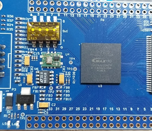
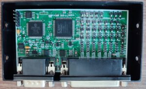
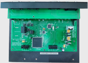 Pic 1. The SUZ control block
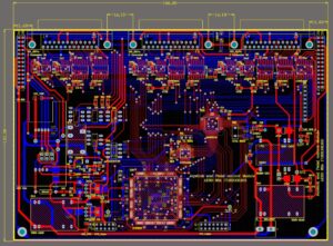
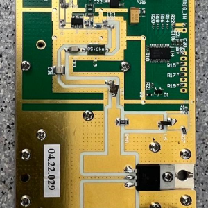
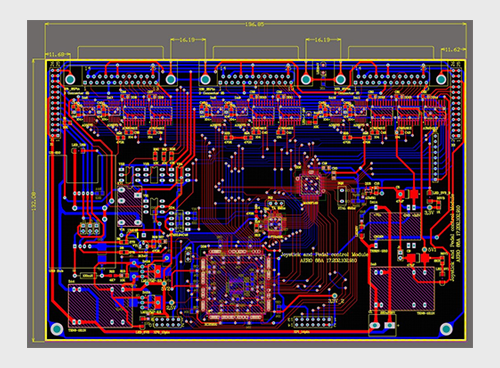
Pic 2. Printed circuit of module AERO 88A 17.202.102.910 of the SUZ control block
MICROCONTROLLERS (MKS)
I. Features:
The MKS receive signals from all panels of the emulator cockpit then transmit them to simulation computers. The MKS also send back control signal from the computers to the panels.
II. Principles:
For proper simulation, the cockpit of emulator requires 60 microcontrollers which can be interchanged. The MKS can be divided into groups. Each group can be controlled by a microcontroller and provided an ID tag. The MKS groups will be connected to RS485 network through 3 network cards (converters) which connect to computers ò simulation system.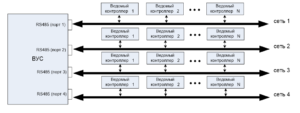
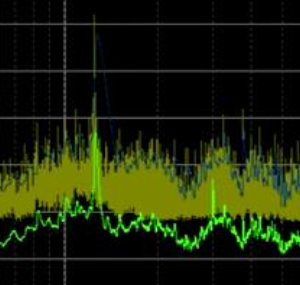
Pic 3. Comunication stucture of MKS.
Communication structure of MKS consits of 4 RS486 networks (Pic 3). Each network can be connect upto 32 MKS.
III. Specifications
| No | Nomenclatures | Units | Values |
| 1 | Supply voltage
– 24V DC – (+12)V DC; – (+5)V DC. |
V V V |
24±5% 12±5% 5±5% |
| 2 | Power consumtion | W | <10 |
| 3 | Operating environment
– Temperature – Humidity |
0C % |
10÷30 < 80 |
| 4 | Storage environment
– Temperature – Humidity |
0C % |
15÷35 < 80 |
| 5 | Continuous ơperating | h | 4 |
| 6 | Life of expectancy | yr | 5 |
| 7 | Dimension (depth x width x height) | mm | 105 x 64 x 20 (±5mm) |
| 8 | Weight | kg | <0.3 |
| 9 | Number of receive and control channel | channel | 32 |
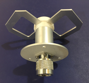
Pic 4. MKS layout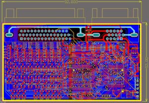
Pic 5. Printed circuit of a module in a MKS