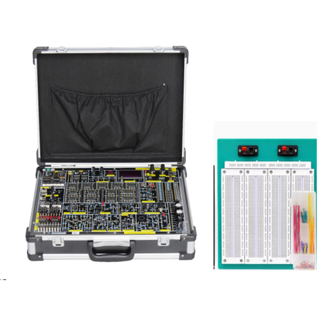
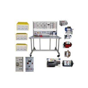
TB-230223-V-090 Analogue/Digital Logic Trainer Set
Specification
– Condition: Brand New and Unused
- The proposed Analogue/Digital Logic Trainer Set should meet the following specification:
1) On board power supply: Variable ± (0 to 15V), 0.5A; Fixed ±5V, 1A with short circuit protection.
2) TTL or CMOS Mode Selector: Switch
3) Built in Function Generator: Sine, Triangle & Square / TTL. Output
Frequency: 1 Hz to 100KHz in at least 5 ranges, with amplitude (10Vp-p max) & frequency control pots.
4) Variable Resistor: 1 x 1Kohm, 1 x 100 Kohm
5) 16 Input Data Switches and 16 output LED status indicators for High/Low indication
6) Two digits of 7 segment LED display.
7) Two Pulser switches with 2 sets of output (A, Inverted A, B, inverted B)
8) Solderless breadboard that comes with 2820 tie points contact
9) Operating Voltage: 220V/AC-50/60Hz, 110V/AC-50/60Hz
10) 1 set of Power Cord Cable
- Technical parameter:
- Power
Input: AAC220V±10%Output:(1)DCV ,±12V/0.2A,DCI≥0.2A(2)DCV,±5V/2A,DCI≥1AA2. Signal source(1)function generator output wave shape: Square wave triangle wave sine wave
Amplitude: square wave triangle wave sine wave : (0 ~ 10 V for peak-peak)
Frequency range: it can be divided to 4 range: 0HZ~200HZ, 200HZ~10KHZ, 10KHZ~100KHZ, 100KHZ~200KHZ (2)DC signal, double way, ±5V, ±0.5V, it can be adjust continuously
- supply 4 single pulse generator 4. Four ways (AT1, AT2, AT3, AT4) sequence generator, and start and stop circuit
- 1HZ~10MHZ pulse output6. 12 ways switch output display circuit
- 6 bits 7 segment LED displayer
- 2 ways BCD code switch 9. The system has many 8P~40P common round hole, IC experiment circuit plug and socket, with resistor for 1K, 10K, 22K, 100K, 680K etc. and contact safety socket, it can connect resistor, capacitor, it can do pulse experiment, digital circuit experiment, logic circuit and many basic experiment.
- 555 timer base circuit with audio output control
- Six high precision digital frequency meter, test range: 0-9.9999MHZ error range: <1HZ(it is designed by CPLD chip) 12. Supply with 3 and a half digital voltage meter13. It has potentiometer group and resistance capacitance and inductance diode electronic component, and easy for students to use.
- Analogue circuit experiment zone is made of single pipe two pipe differential amplifiers and integrated op-amp rectifier voltage filter of circuits, etc
- Experiment area use metal needle, use a medium sized hole, never oxidation, beautiful and beautiful, practical strong, experiment with wires plug metal paint process, inserted more convenient, more reliable contact, and long service life II. Experiment content Digital part experiment contain:1.TTL logical gate parameters test and use
2.CMOS Integration logic gate of the test
3.Gate circuit logic function test 4.Common combination logic function components test5.Data collect and application 6.Blood type relationship detection circuit and voting circuit 7.RS function of the trigger and test 8.JK trigger logic function and main parameters test
9.The shift register function test
10.Decade computer(CMOS)11.Asynchronous counter 12.Synchronous counter
13.Count decode display circuit experiment
14.555 Integrated timer and application 15.Sequential detector
16.Follow type is A/D conversion circuit 17.Artificial control traffic light controller 18.Automobile tail light control circuit 19.Digital circuit design20.Timing circuit testing and research
- Wave shape generate and monostable trigger
- A/D convert circuit
- D/A convert circuitAnalog part experimental contents:
1, Rectifier voltage filter and parallel circuit
2, Series voltage stabilizing circuit
3, Integrated voltage stabilizing circuit
4, Integrated power amplifier
5, Complementary symmetry power amplifier
With bread board and expand chip
3.Supplied with English user manual
Supplied with English demo video
Supply free online training for 1 day


