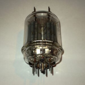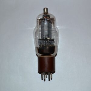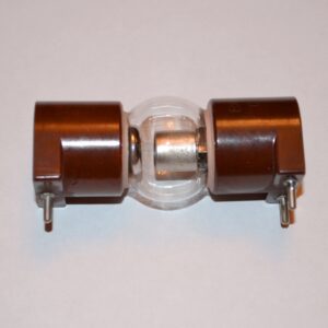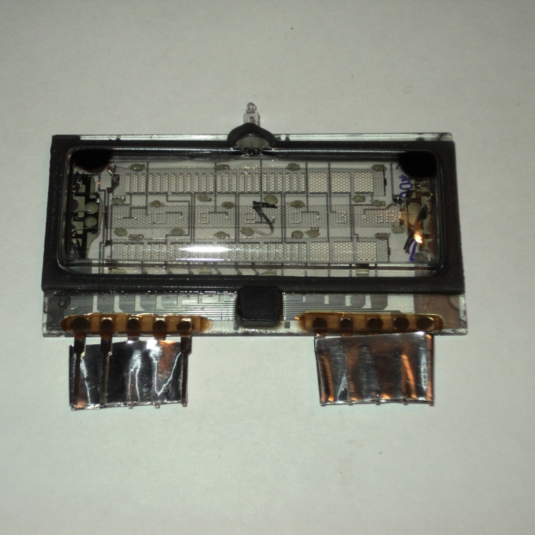
stereo indicator of the level of the “flooded” sector
The indicator body is glass, flattened, rectangular in shape;
conclusions – hard plate tinned.
To control the operation of the indicator, a chip is built into it.
The weight of the device is not more than 40 g.
The scale indicator of the level of two signals is designed for
work in high-quality household sound amplification equipment.
Main Features:
Luminance, cd/m2, at least, of the anodes-elements
green glow—250
red glow—70
Luminance, cd/m2, not less, at the end of the guaranteed operating time for anodes-elements
green glow—125
red glow—35
Contrast ratio, %, not less than—60
Viewing angle, deg., not less than—40
Dimensions of the information field, mm—54×17
Number of controlled anodes-elements—23
Rated cathode glow voltage, V—2.4
Voltage on the anode elements, V—27…33
Cathode glow current, mA
limit values—140…170
nominal value—160
Number of incandescent inclusions, not less than—104
Ready time after switching on, s, no more than—0.1
Guaranteed operating time, h, not less—30 000
Operating range of ambient temperature, °C—/-45 …+40
Main characteristics of the integrated circuit:
Supply voltage, V—27…-33
Voltage between the cathode and the common wire, V
(The difference between the supply voltage of the control chip and
the voltage of the cathode – common terminal should not be less than 3 V)—24…-30
The voltage of the channel selection signal V, for the level
high, not less than—1
low, no more than—9
Voltage at control inputs 1 and 2, V—0…-8
Leakage current, mkA, no more,
by switch input—5
by analog inputs—10
Limit values of parameters:
Cathode glow voltage, V—2…2.65
The largest negative supply voltage of the integrated circuit, V—38
The greatest negative voltage between the cathode and the common wire, V—30
The greatest negative voltage at inputs 1 and 2 of the control, V—14
It is recommended to attach the indicators in the equipment by gluing the balloon
to the edges of the cutout in the raised panel for the dimensions of the scoreboard with “Elastosil” glue.
Mechanical mounting or mounting on terminals soldered on the board is not allowed.
The position of the indicator during operation is any.
The foreign equivalent is FG28SB1.