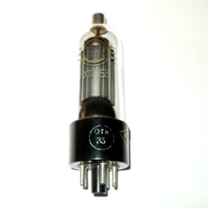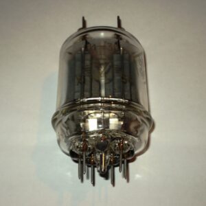
A series of numbers. the indicator is gas-discharge.
Recommendations for use:
Working position — any.
Cooling is natural.
When installing the indicator on printed circuit boards, bending of the pins is allowed.
Fastening by pins is not allowed.
The indicator is connected to the control circuit through tinned contact petals by soldering
tin-lead solder.
The indicator must be operated in multiplex mode.
Digital multi-digit gas discharge indicator IGP-17 is designed for
to display information in the form of digits from 0 to 9 (and decimal places) in
each of the 16 digital digits and additional information in the service
the category in the media of displaying information for individual and group use.
The case is flat, glass. Weight not more than 150 g.
Basic technical data:
Luminance—> 100 cd/m2
Nominal luminance at maximum current—170 cd/m2
Horizontal viewing angle at an observation distance of0.6-0.8 m—> 120°
Auxiliary cathode power supply voltage (constant)—> 190 V
Discharge voltage (pulse amplitude)—< 190 V
Discharge maintenance voltage(pulse amplitude)—< 170 V
Offset voltage on the segments relative to the anodes (constant)—< 120 V
Indication current(average value):
single segment—< 25 µA
decimal point—< 18 µA
Time interval between pulses,
supplied to the electrodes of two adjacent acquaintances—> 35 microseconds
Ready time at 40 lux illumination—< 1 s
Minimum operating time—5000 h
Parameters that change during the minimum operating time
pulse voltage of discharge occurrence—< 190 V
average display current:
single segment—< 30 µA
decimal point—< 21 µA
indicator brightness—> 90 cd/m2
Shelf life—at least 8 years
Vibration loads(1-2000 Hz)—< 5g
Multiple shock loads (impact duration 2-15 ms)—< 15g
Single shock loads(impact duration 2-6 ms)—< 75g
Ambient temperature:
during operation—+1 …+50°C
during transportation—/-60 …+50°C
Relative humidity—no more than 98%
Reduced atmospheric pressure—400 mm Hg.
Maximum permissible electrical mode:
The lowest switching voltage of the power supply—190 V
The lowest constant voltage of the power supply
auxiliary cathodes—190 V
The greatest constant bias voltage on the segments
regarding anodes—120 V
Operating current of one segment:
average—25…40 µA
pulse—300…700 ma
Decimal point operating current:
average—13…20 mkA
pulse—200…400 ma
Operating current of the auxiliary cathode—7…15 Ma
The shortest pulse duration of the power supply voltage—200 microseconds