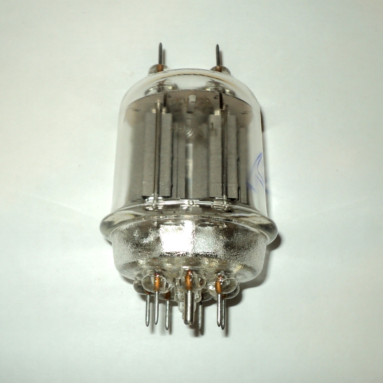
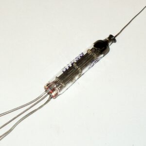
double generator tetrode
Tetrode GU-29 is designed to enhance power and generate
high frequency oscillations. It is used in transmitting devices.
The cathode is an oxide of indirect incandescence. Works in any position.
It is available in a glass design. The service life is not less than 500 hours.
The terminals of the electrodes are pin. Pins 7. Interelectrode capacitances, pf
Output 15 ± 2. The output is 7 ± 2. The pass-through is not more than 0.1.
Rated electrical data
Incandescent voltage, v ……… 6,3 or 12.6
Incandescent current at parallel connection of heaters, a ………. 2,25 ± 0,25
the incandescent current when the heaters are connected in series, and ……… 1,125 ± 0,125
Voltage at the anode, v ……. 400
Voltage on the second grid, v ……… 225
Current in the anode circuit of each tetrode *, ma … 60 ± 22
Current in the circuit of the second grid, ma ……. 10
The steepness of the characteristics of each tetrode, ma/v ………. 8.
The gain of each tetrode relative to the second grid ……. 9
Oscillating power **, w ….. 45
Maximum permissible electrical values
The highest incandescent voltage at parallel connection of heaters, v ……… 7
The lowest incandescent voltage when the heaters are connected in parallel, in ……… . 5,7
The highest incandescent voltage when the heaters are connected in series, in …….. 14
The lowest incandescent voltage when
the heaters are connected in series, v …….. 11.4 The highest voltage at the anode, v
……. 750
The highest voltage on the second grid, v …………. 225
The highest power dissipated on the anodes for a long time, w ……………. 40
The highest power dissipated for a long time on the second grid, w …………. 225
The greatest constant voltage between the cathode and the heater, v ………… 100
Maximum operating frequency, Mhz …….. 200
Maximum operating temperature of the cylinder, °C . . . . 100
The greatest leakage current between the cathode and the heater, mka ….. 175
* Provided: for the test tetrode, the voltage at the anode must
be 250 v, 175 v on the second grid, minus 11 v on
the first grid, minus 100 v on the first grid of the untested (second) tetrode.
** In a push-pull circuit in self-excitation mode. The total current in
the anode circuit is 250 ma, the current in the second grid circuit is no more than 35 ma, in the first
grid circuit from 10 to 15 ma, the voltage on the second grid is 225 V, the resistance in
the first grid circuit is from 5 to 12 kohm, the oscillation frequency of the circuit is 200.

