ASR2035 Electrical Faults in Refrigerant Compressors Vocational Training Equipment Compressor Training Equipment
Learning Objectives / Experiments
– Electrical connection of refrigerant compressors
– Read and understand electrical circuit diagrams
– Design and operation of the electrical components of a refrigerant compressor
* start-up capacitor
* start-up relay
* operating capacitor
* overheat protection
* main contactor
* automatic fuse
– Fault finding in electrical components
* in idle state
* under mains voltage
Specification
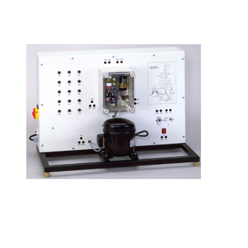
[1] Experimental unit from the practical series for the training of mechatronics engineers for refrigeration
[2] Investigation of the electrical components for the operation of a refrigerant compressor
[3] Real refrigerant compressor from practice
[4] Electrical components for the start and operation of the compressor arranged in the transparent switch cabinet
[5] General safety devices mounted clearly visible
[6] Circuit diagram depicted on the front panel
[7] Identification of 15 faults: multimeter measures voltages or resistances at the lab jacks
Technical Data
Refrigerant compressor
– power consumption: approx. 870W
Electrical components for the compressor
– start-up capacitor
– start-up relay
– operating capacitor
– overheat protection (bimetallic)
General safety devices
– main contactor
– automatic fuse
Dimensions and Weight
LxWxH: 900x400x650mm
Weight: approx. 60kg
Connections
230V, 50/60Hz, 1 phase or 120V, 60Hz, 1 phase

