ASR2034 Electrical Fault in Simple Air Conditioning Systems Didactic Equipment Refrigeration Training Equipment
Learning Objectives / Experiments
– electrical design and principle of operation of simple air conditioning systems
– read and understand electrical circuit diagrams
– design and operation of electrical components in an air conditioning system
* start-up capacitor
* start-up relay
* overheat protection
* main contactor
* automatic fuse
* on/off switch
* speed switch
* thermostat
– fault finding in electrical components
* in idle state
* under mains voltage
Specification
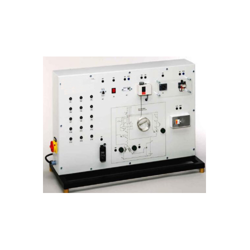
[1] experimental unit from the practical series for the training of mechatronics engineers for refrigeration
[2] simulation of the electrical circuit of a simple air conditioning system for cooling
[3] real control circuits with electrical components, simulated load circuits
[4] electrical simulation of compressor and fan
[5] temperature control with thermostat and compressor
[6] fan with 2 adjustable speeds
[7] operating states of the simulated components indicated via lamps in the circuit diagram
[8] circuit diagram depicted on the front panel
[9] identification of 15 faults: multimeter measures voltages or resistances at the lab jacks
Technical Data
Simulated compressor
– start-up current: > 3A
Electrical components for the compressor
– start-up capacitor
– start-up relay
– overheat protection (bimetallic)
Electrical components for the fan
– on/off switch
– speed switch
Thermostat: -5…35°C
General safety devices
– main contactor
– automatic fuse
LxWxH: 900x400x650mm
Weight: approx. 30kg
Required for Operation
230V, 50/60Hz, 1 phase or 120V, 60Hz/CSA, 1 phase

