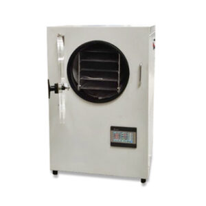
ASR2015 Electrical Connection of Refrigerant Compressors Didactic Equipment Refrigerator Training Equipment
Learning Objectives / Experiments
– read, understand, wire and test electric circuit diagrams for refrigerant compressors
– design and operation of electrical components of refrigerant compressors
* start-up capacitor
* start-up relay
* overheat protection
* automatic fuse
* pressure switch
* thermostat
– design and testing of a safety chain
– representation methods in electrical engineering
* symbols
* circuit diagrams
– safety aspects when handling mains voltage
Specification
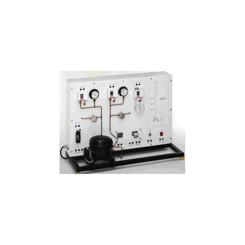
[1] experimental unit from the practical series for the training of mechatronics engineers for refrigeration
[2] correct electrical connection of a refrigerant compressor
[3] refrigerant circuit with compressor, receiver, 2 valves and 2 manometers to investigate pressure switches on the delivery and intake sides
[4] electrical components for the start and operation of the compressor mounted clearly visible
[5] lab jacks and cables to connect the electrical components
[6] operation of a thermostat
[7] circuit diagram on the front panel for easy identification of the components
[8] refrigerant AR134a, CFC-free
Technical Data
Refrigerant compressor
– power consumption: approx. 165W
Receiver: 0,8L
Manometer measuring ranges
– delivery side: -1…24bar
– intake side: -1…9bar
Pressure switch control range
– delivery side: 8…32bar
– intake side: -0,9…7bar
Thermostat: -5…35°C
Electrical components for the compressor
– start-up capacitor
– start-up relay
– overheat protection (bimetallic)
– automatic fuse
Dimensions and Weight
LxWxH: 920x410x660mm
Weight: approx. 45kg
Required for Operation
230V, 50Hz, 1 phase

