AZE4123 Demonstration Panel for the Electric Testing Carried Out in A Building teaching aid equipment Electrician Trainer
INTRODUCTION
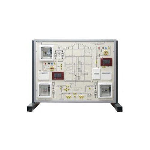
This panel can be used by teachers for their lessons and by students for an easy learning and testing on electrical prevention systems supplying them with the means for verifying the rule of art and the relevant technical standards.
Actual electrical devices installed, already connected with each other, enable to check the operation, besides carrying out the measurements of all the electric parameters with conventional instruments.
The panel is made of insulating material and it represents the support of the necessary devices for carrying out the testing programme.
The apparatuses are represented on the panel with their standardized international symbols and electrical block diagram, for an easy reference with their lay-out.
Furthermore, when necessary, test points correspond to standardized educational terminals with high protection degree against accidental contacts.
TRAINING PROGRAM:
This panel can be used to defi ne the electrical installations of a building (power distribution via TT system) with reference to the following topics:
Electrical installation of the building complying with guide
Graphic symbols for installation plans
Branch exchange for a fl at
Meter room and riser
Earthing system for the block of fl ats
Furthermore, this panel is designed to deal with topics,
visual checks, tests concerning:
Protection systems against direct and indirect contacts
Choice of conductors, current-carrying capacity and voltage drop
Testing the paths of conductors and their suitability and duct diameter and removableness of conductors
Suitability of materials and of equipment
Protection and breaking devices
Identifi cation of neutral and earth conductors
Suitability of the connections of conductors
Continuity of protection and equipotential conductors
Isolation resistance
TECHNICALSPECIFICATIONS:
Framework is made of sheet steel chemically treated and painted with several coats of epoxy varnish; its base is provided with rubber feet and it can be positioned on a working top.
All the necessary electric components for the correct power supply of circuits are included in the panel.
Main components installed:
1 single-phase isolation transformer 230 V / 230 V 230 VA
2 simulators of earth plate with resistors of 2 Ω, 20Ω, 200 Ω, 2 kΩ
1 simulators of resistance of protection conductor with
resistors of 0.1 Ω, 1 Ω
1 simulator of extraneous conducting part with resistances of
200 Ω, 1000 Ω, 5000 Ω
1 magnetothermal circuit breaker 2 x 2 A “C”
1 magnetothermal circuit breaker 2 x 1 A “C”
1 differential circuit breaker 2 x 1.6 A “C” / 30 mA “AC”
1 magnetothermal and differential circuit breaker 2×25 A/30 mA “A”
1 protection and control switch – 2P +Earth
Two 2-pin sockets – 10/16 A, 2P + Earth
2 simulators of isolation earth fault in power consuming
Device with resistors of 50 kΩ, 15 kΩ, 5 kΩ, 1500 Ω, 500 Ω,
and bolted fault
Dimensions of demonstration panel: 800 x 600 mm
Dimensions of framework: 840 x 450 x 680 mm
Net weight: 33 kg
SUPPLIED ACCESSORIES:
1 single-phase power cord with UNEL plug
8 jumpers with safety plugs (Ø 4 mm) for assembling the
various installation conditions
RECOMMENDED ACCESSORIES AND
SOFTWARE:
Multi-function microprocessor instrument for electric testing
Digital current probe
Digital autoranging multimeter
Circuit design, simulation and animation software for electrical engineering projects
POWER SUPPLY:
230 V / PE 50-60 Hz; Max. absorption: 250 VA

