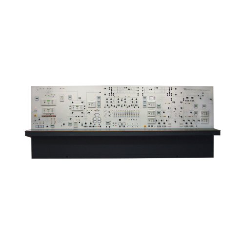
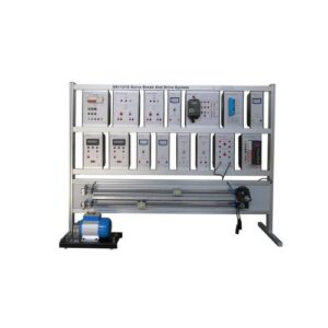
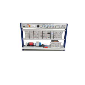
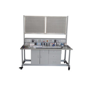
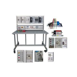
AZE8550 Power System Line Trainer (APSS1): A self-contained unit that simulates all parts of electrical power systems and their protection, from generation to utilization Teaching Equipment Vocatioal Traning Equipment
For simulation in the electrical consumption, it should have lamps and test loads.
The main components of the module must be:
01 charge controller of 10A for the photovoltaic panels
01 charge controller for the wind generator
01 Single phase Plug
04 Lamp modules
01 stationary battery 12 Vcc 18Ah
01 single phase distribution module
01 bipolar circuit breaker
02 duplo switch modules
01 grid tie micro inverter 2030 W
01 simulation module with power supply single phase
01 Data acquisition module that can allow voltage and current readings using voltage and current transducers
02 Photovoltaic panels polycrystaline 95 Wp
01 solar module polycrystaline 10 W with halogen lamp
01 wind generator with power 350 W
01 wind generator module coupled to three phase motor of 1.5 steam horse
01 pumping bank module photovoltaic
01 all in one with Windows System (PC)
01 Monitoring software and operation of the whole Module
All the module structure should be in anodized aluminum, carbon steel and medium density panels (MDP Panels)
Power supply with protection against short circuit, overcharge and electrical discharges
Adjustable Supporting beams to hold and fix the adjustable modules
All the modules should be AIP20 protection, high resistance lamination, and laser marked identification with back holding mounting
The supervision software should work like this:
For the learning experience in the selection of the circuit as “Grid Tie” it should visualize the diagram of the circuit, showing in real time the values of voltage, current and power of each part of the circuit, indicate in a graphical diagram the relations between the generation and consumption of energy, and the net electrical energy remaining received or transmitted from the electrical network.
For the learning experience in the selection of circuit “Off Grid” it should visualize a diagram of the circuit, showing in real time the values of voltage, current and power for each part of the circuit.
For the learning experience in the selection of photovoltaic pumping, it should visualize a diagram of the circuit, showing the values of voltage, current and power of each part of the circuit, besides the volume of water in the upper water deposit, medium caudal, total performance, looses and time of the experiment, all shown and visualized in real time.
01 photovoltaic pumping module: mounted in autosupporting structure of anodized aluminum and should allow the water pumping using a photovoltaic panel

