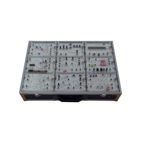
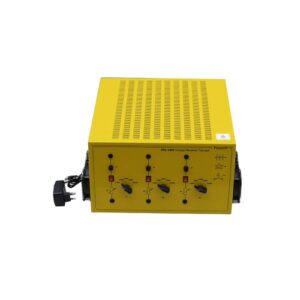
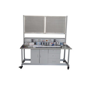
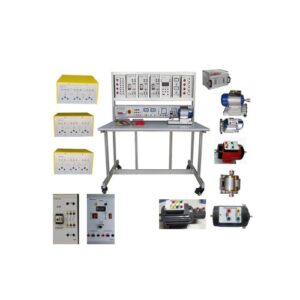
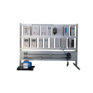
AZE3382 AM trainer Teaching Equipment Electrical Laboratory Equipment
I.Performance Indicators
1.Signal source indicators
u High frequency signal source:
Output frequency range: 400KHz ~ 45MHz (continuously adjustable) (minimum step 1KHZ)
Frequency stability: 10E-4
Output waveform: sine wave, harmonics≤-30dBc
Output amplitude: 1mVp-p ~ 1Vp-p (continuously adjustable)
Output impedance: 50Ω
u Low frequency signal source:
Output frequency range: 200Hz ~ 10KHz (continuously adjustable, square wave frequency up to 250KHz)
Frequency stability: 10E-4
Output waveform: sine wave, square wave, triangle wave
Output amplitude: 10mVp-p ~ 5Vp-p (continuously adjustable)
Output Impedance: 100Ω
2.Functional indicators
Each module of the experimental box has a good systematicness, and eight modules can be combined into five typical systems:
(1) Medium wave AM transmitter (525KHz~1605KHz)
(2) Superheterodyne AM Receiver (525KHz~1605KHz, IF 465KHz)
(3) Half-duplex FM radio (10MHz~15MHz, IF 4.5MHz, channel spacing 200KHz)
(4) Phase-locked frequency synthesizer (frequency step 40KHz ~ 4MHz variable)
(5) Superheterodyne FM radio (88MHz~108MHz, IF 10.7MHz)
II.Module Introduction
Frequency meter module: It is mainly used for frequency measurement in the experiment. 8 digital tubes are used to display the frequency count value, and the unit indicator light is used to indicate the current value unit.
Signal source module: Provides two signal sources of high frequency and low frequency, the output amplitude of the signal source is continuously adjustable, and the internal modulation function is attached
Small-signal frequency selective amplifier module: including single-tuned amplifier circuit, capacitively coupled double-tuned amplifier circuit, integrated frequency-selective amplifier circuit, automatic gain control circuit (AGC) and other four circuits
Sine wave oscillation and VCO module: including LC oscillation circuit, quartz crystal oscillation circuit, voltage-controlled LC oscillation circuit, varactor diode frequency modulation circuit, etc.
Amplitude modulation and demodulation module: including analog multiplier amplitude modulation (AM, DSB, SSB) circuit, diode peak envelope detection circuit, triode small signal envelope detection circuit, analog multiplier synchronous detection circuit and other four circuits
FM frequency discrimination module: It includes three circuits, such as quadrature frequency discrimination (product phase frequency discrimination) circuit, phase-locked frequency discrimination circuit, and basic phase-locked loop.
Mixing and frequency conversion module: including diode double-balanced mixing circuit, analog multiplier mixing circuit
High-frequency power amplifier module: including nonlinear class C power amplifier circuit, linear broadband power amplifier circuit, integrated linear broadband power amplifier circuit, collector amplitude modulation circuit and other four circuits
Radio module: including triode frequency conversion, AM radio, FM radio
Comprehensive experimental module: It includes four kinds of circuits, including microphone and music amplifier circuit, audio amplifier circuit, antenna and half-duplex circuit, frequency divider circuit, etc.
III. Experiment content
Experiment 1 Small-signal tuning (single, double tuning) amplifier experiment
Experiment 2 Integrated frequency selective amplifier experiment
Experiment 3 Diode double-balanced mixer experiment
Experiment 4 Analog Multiplier Mixing Experiment
Experiment 5 Three-point sine wave oscillator (LC, crystal) experiment
Experiment 6 Crystal Oscillator and Voltage Controlled Oscillator Experiment
Experiment 7 Nonlinear Class C Power Amplifier Experiment
Experiment 8 Linear Broadband Power Amplifier Experiment
Experiment 9 Collector Amplitude Modulation Experiment
Experiment 10 Analog Multiplier Amplitude Modulation (AM, DSB, SSB) Experiment
Experiment 11 Envelope Detection and Synchronous Detection Experiment
Experiment 12 Varactor diode frequency modulation experiment
Experiment 13 Quadrature frequency discrimination and phase-locked frequency discrimination experiment
Experiment 14 Simulate phase-locked loop experiment
Experiment 15 Automatic Gain Control (AGC) Experiment
Experiment 16 MW AM transmitter assembly and debugging experiment
Experiment 17 Superheterodyne AM Receiver Assembly and Debugging Experiment
Experiment 18 Phase-locked frequency synthesizer assembly and debugging experiment
Experiment 19 Half-duplex FM wireless walkie-talkie assembly and debugging
Experiment 20 Superheterodyne FM Radio System Experiment

