Military Ground Test Systems
The system includes
Test system AGT-1
Test system AGT-2
Test system AGT-3
Test system AGT-4
Test system AGT-5
Test system AGT-6
Test system AGT-7
Test system AGT-8
Test system AGT-9
Measuring device IP-1
Measuring device IP-2
Gyro test table UPG-8
Pivoting console KP-8
Test system AGT-4М
ANAXI -VIDEO vision system
ANAXI-T-KONUS main rotor blades tracking system
General information
1. Test systems AGT-1 – AGT-9
These system are automated systems to monitor and measure electrical parameters of on-board electrical equipment, radios and instrumentation of Helicopter (Mi-8, Mi-17, Mi-171, Mi-172, AH-64D, H-47, H60, OH-58D,..), Aircraft (Sukhoi series, F15,F16, F18, …) and Military ships (Equipment can be adjusted according to customer requirements)
All system use 220V 50Hz AC obtained from industrial network.
Sources of dedicated power supply for tested equipment make a part of hardware.
Equipment tested and test systems are connected by harnesses (cables, hoses) designed to prevent wrong connection.
Test systems consist of modules that are programmable electronic devices managed by industrial computer. The system forms output test signals (voltages, frequencies, currents, pressures etc.) that simulate functioning of testing equipment a manufacturer uses and recommends in its normative documents (Maintenance Manual etc.), and measures output signals by built-in metering equipment.
PC-installed system and applied software manages hardware of test systems. Software offers user interface to operator and helps in using hardware and testing of the equipment.
User interface allows:
Auto diagnostics of the system
Entering particulars of the equipment tested
Opting for auto or manual mode of testing
Presenting of parameters measured, informing the operator on unacceptable electrical parameters of the equipment
Providing the operator with symptoms-based list of probable faults, editing and adding more symptoms and defects
Printing ready final reports of standard form; – saving testing results and equipment details in database
Making regular certification of the system.
Hardware of the system measures electrical parameters of the equipment tested and forms control actions required for testing.
Hardware includes:
Industrial PC
Data acquisition board
Input/output modules
Controllable power sources
Relay board
Uninterruptible power source (UPS)
During the testing, the operator may adjust and set the equipment according to its operation Manual.
User interface and industrial computer facilitate the job of the operator, intensify testing procedures, and help in training of newly employed specialists.
The system augments working efficiency, reduces effect of human factor upon procedures and results of testing. Its decisive advantage consists in saving information on results and item under control and in fast search of the information required.
Uninterruptible power source assures long-term protection of the system against power failures, voltage reduction, short-term voltage fails and voltage/current jumps. Additionally, it filters interferences in power supply circuit and protects the equipment of any hazards in case of an unintentional disconnection of equipment from the circuit.
Front and rear doors in the housing 1 afford an access to cabling and hardware of the system.
Printer prints out ready final reports of the results of testing.
Weight of the working place is approximately 300 kg.
2. Measuring device IP-1
Measuring panel IP-1 allows an input control of on-board equipment, a functional testing of on-board equipment during maintenance, for adjustment and repair.
IP-1 verifies and tests the exhaust gas temperature indicating system 2IA-6, monitors and measures its parameters in accordance with the Operational Manual of the system.
3. Measuring device IP-2
Measuring device IP-2 allows an input control of on-board equipment, a functional testing of on-board equipment during maintenance, an adjustment and repair.
IP-2 monitors and measures the parameters of the set in accordance with its Operational Manual.
4.Gyro test table UPG-8
A gyro test table checks and tests gyro instruments by longitudinal and lateral tilting, rotation and swinging. It can be used both either independently with a control panel, or as a part of AGT-8 test system.
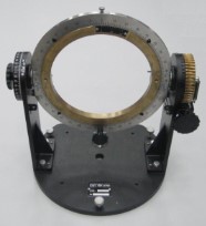
5. Pivoting console KP-8
A mount creates rotation angles about longitudinal (roll angle) and lateral (pitch angle) axes of an instrument tested
6.Test system AGT-4М
A complex, designed for on board of Mi-17, Mi-171, Mi-172, Mi-8, Mi-8MTV, Mi-8MT, Mi-8AMT helicopters performs schedule maintenance of an electrohydraulic autopilot
7. ANAXI -VIDEO vision system
An equipment offers an image of a pointer and a limb of an inlet guide vane (IGV) of TV3-117 engine. It consists of:
– twin camera head with a connecting cable;
– processing and displaying unit;
– power harness;
– trunk.
8. ANAXI-T-KONUS main rotor blades tracking system
A system performs on-ground or in-flight remote measurement of blade tips positions while track-ing main rotors of 2 to 8 blades
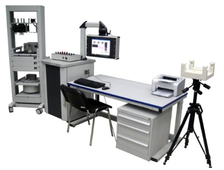
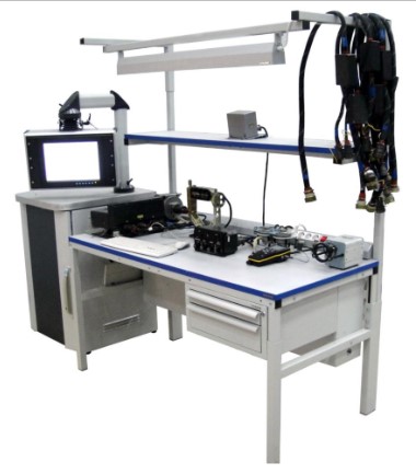
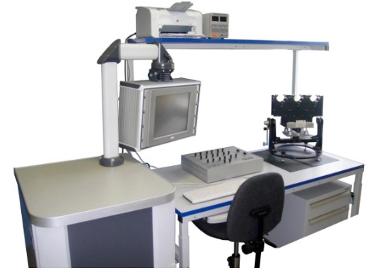
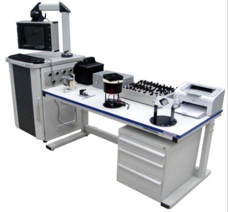
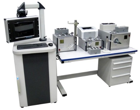
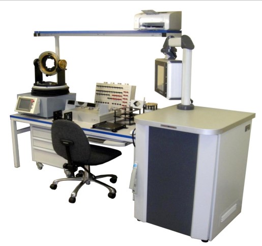
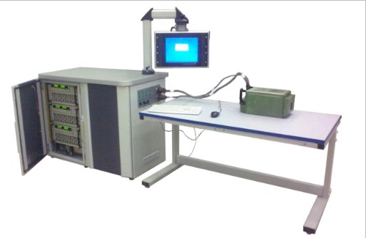
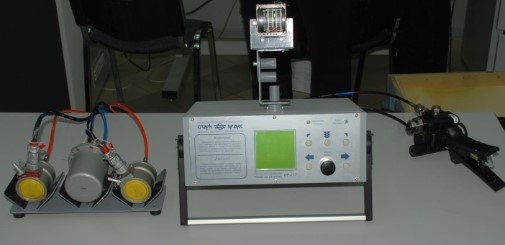
Configuration
All systems include (as Fig.1 shows):
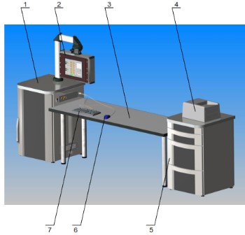
– Housing 1 (left pedestal): for hardware part of the system
– Operator’s monitor (installed in Opt panel for changing of the angles of its turn and tilt)
– Table for equipment tested, holders and supports
– Keyboard
– Computer “mouse”
– Cable assemblies (cables, hoses) to connect equipment;
– Printer (on request)
– Housing 2 (right pedestal): for documents, cables, hoses to connect equipment, tools and spare
– Parts (on request, of various designs)
A separate table, equipment racks and shelves (on request) can come in various designs.
The individual composition of the systems AGT-1 – AGT-9
Test System AGT-1
Equipment tested:
a) Radio station Baklan-20
b) Radio station Orlan-85СТ
c) Radio station Yadro-1A, Yadro-1A1, Yadro-1G, Yadro-1G1
d) Radio altimeter РВ-3, РВ-3М
e) Radio altimeter А-037
f) Voice recorder P-503B
g) Voice recorder МС-61
h) Warning system Almaz UP
i) Voice warning system RI-65-B
j) Intercom system SPU-7
k) Product Almaz UPM
Test system AGT-2
Equipment tested:
a) Doppler system DISS-15
b) Doppler system DISS-32-90A
Test system AGT-3
Equipment tested:
a) Automatic direction finder ARK-15M
b) Automatic direction finder ARK-9
c) Automatic direction finder ARK- UD
d) Automatic direction finder ARK- U2
Test system AGT-4
Equipment tested:
Autopilot AP-34B series 2:
-Control unit; – Control panel
– Force-balance transducer
– Trim indicator IN-4
– Amplifiers unit BUNPP 1479
– Filter unit BF-34 – Coupling unit BS-34
– Ready signal unit BSG – Amplifier 1602
– Force-balance transducer 9A2.032.02
Test system AGT-5
Equipment tested:
a) Airspeed indicators US-450K, US-350K
b) Rate-of-climb indicators VAR-30M (MK), VR-10MK
c) Altimeters VD-10VK, UVID-30-15, UVID-30-15-2, UVID-15F, VJeM-72F, VJeM-72
d) Altitude transmitters DVK
e) Pressure transducers IKD-27 Da 220÷780, IKD-27 Da 400-830
f) Altitude controller KB-11;
g) IAS controllers KZSP (with BSG ready-signal unit)
h) Altitude controllers KZV-0-15 (with BSG ready-signal unit)
i) Ready signal units BSG
k) Altitude transmitters DV-15MV k) Indicated airspeed transmitters DAS
l) Pressure switches SD-29A
m) Indicated airspeed transmitters DPSM-1
n) BSPI-4-2 and PU-25 units of BUR-1-2 (FDR) set (calibration) for the channels of DPSM-1, DAS, DV-15MV transmitters
Test system AGT-6
Equipment tested:
a) Vibration indicating system IV-500A (IV-500E) 2 ser.:
– Electronic unit BJe-9A 2 ser., BJe-9E 2 ser.
– coupling unit UsS-6-2 2 ser.
– Vibration pickup MV-03-1
b) Fire detection system SSP-FK ser. 2, SSP-FK:
– Actuating unit SSP-FK BI 2 ser.
– Fire detectors
c) Thermoelectric thermometer TST-282C:
– meter TST-2
– Thermocouple T-82K
d) Exhaust gas temperature indicating system 2IA-6:
– Indicator 2UT-6K
– Amplifier 2UJe-6B
– Compensating block PK-6
e) Flight data recorder BUR-1-2, BUR-1-2ZH:
– Control panel PU-25
– Flight data storage unit BSPI-4-2
– Module M11A;
– Protected recorder unit ZBN-1-1 – Position transmitter MU-615A
– Linear accelerometer MP-95
– Compensating accelerometer ADIS-2-2, ADIS-2-3
f) Temperature regulator RT-12-6 2 ser.
g) Temperature regulator URT-27 5 ser.
h) Temperature regulator TJeR-1M;
i) Warning and caution system SAS-4, SAS-4M:
– Warning signal unit BAP-1, BAP-1M
– Caution signal unit BU-1, BU-1M
– Switching unit BK-7, BK-7M j) Anti-collision light MSL-3-2s
k) 3-phase static inverter PTS-800BM.
Test system AGT-7
Equipment tested:
a) Magnetic drag-type tachometer ITJe-1, ITJe-2:
– Indicators ITJe-1, ITJe-2
– Tachometer generators D-1M, D-2M
b) Fuel quantity indicating system SKJeS-2027 A, B, V, G:
– Indicator BJe-09K
– Switch P-8U
– Rheostat fuel quantity transmitters
– Simulator IDP
c) Engine pressure ratio indicator set IR-117:
– Indicator UR-117
– Pressure probe PM-10MR
d) Engine gauge units JeMI-3RVI, JeMI-3RI. JeMI-3RTI:
– Indicators UI3-3, UI3-6
– Transmitters ID-3, ID-8, IMD-8, ID-100
e) Pressure gauge DIM-3, DIM-8, DIM-100:
– Indicators UI1-3, UI1-8, UI1-100
– Transmitters ID-3, ID-8, ID-100
f) Air pressure gauges MVU-100, MA-60
j) Heat-resistant non-remote pressure gauge NTM-100
h) Temperature probes P-2, P-77
i) Multi-purpose electrical thermometer TUJe 48:
– Indicator TUJe-48
– Temperature probe P-1
g) Pressure switches MST-25, MST-25A, MST-35, MST-35A, MSTV-2.5, MSTV-2.5A
k) Electrical thermometer TV-19: – Indicator TV-1 – Temperature probe P-9T
Test system AGT-8
Equipment tested:
Top of Form
a) Gyro horizons AGK-77-15, AGR-74-15, AGB-3K, AGB-96D, AGB-96R;
b) Compass system GMK-1A, GMK-1AJe, GMK-1AS, GMK-1G, GMK-1GJe, GMK-1AS:
– control panel PU-26, PU-26Je, PU-26S, PU-27, PU-27Je
– Directional gyro GA-6
– Slaving mechanism AS-1
– Compensator KM-8 (KM-8S)
– Flux-gate detector ID-3
– Radio magnetic indicator UGR-4UK series 3, UGR-4U series 3
– Coupling module BS-1
c) Rate gyro DUS-1209E, DUS-1209G, DUS-1209K
d) Erecting cut-out switch VK-53JeRSH, VK-53JeRV, VK-53JeRB
e) Attitude monitors BKK-18
f) Power fails relay SNP-1
g) Position indicator UP 21-15
– Position indicator IP 21-15
– Sensor DS-11
h) Electric turn indicator JeUP-53
i) Rotor pitches indicator USHV-1:
– Indicator USHV-1
– Transmitter UZP
g) Limit bank comparator and warning unit BSPK-1
Bottom of Form
The system employs gyro test table UPG-8 and pivoting mount KP-8 that may be used as separate monitoring and metering tools.
Test system AGT-9
Equipment tested:
a) Single-phase static converter SPO-9
b) Single-phase converter PO-500A
c) Single-phase converter PO-600S
d) Single-phase converter PO-750A
e) Single-phase converter PO-1500, PO-1500A
f) Three-phase static converter PTS-800BM
g) Three-phase converter PT-125C series 2,3,4
h) Three-phase converter PT-200C
i) Three-phase converter PT-500C, PT-500CB
k) Three-phase converter PO-1000CS
l) Single-phase static converter POS-1000B
Measuring device IP-1
Purpose. Measuring panel IP-1 allows an input control of on-board equipment, a functional testing of on-board equipment during maintenance, for adjustment and repair.
IP-1 verifies and tests the exhaust gas temperature indicating system 2IA-6, monitors and measures its parameters in accordance with the Operational Manual of the system.
IP-1 uses 100 – 240 V, 50/60 Hz power.
The tester provides an alternative to the following equipment:
– Plant UPT-1M
– Reference instrument KP-5
– Thermometer with 0.1 value of scale
– Resistance box, accuracy class 0.02
– Multimeter C-4352
– DC potentiometer, accuracy class 0.05
– Source of adjustable voltage
– Galvanometer, sensitivity 5×10 A/scale (not lower)
– Standard cell
Measuring device IP-2
Measuring device IP-2 allows an input control of on-board equipment, a functional testing of on-board equipment during maintenance, an adjustment and repair.
It checks the set of engine pressure ratio indicator that consists of:
– An altitude transmitter DVKr;
– Two pressure probes PM-10MR;
– An engine pressure ration indicator UR-117.
IP-2 monitors and measures the parameters of the set in accordance with its Operational Manual. The tester uses 100–240V, 50/60 Hz power ,with grounding.
The measuring device provides an alternative to the following equipment:
– Resistance box, accuracy class not lowers than 0.1
– DC source 27V±10 %
– AC or DC source of 5.5V voltage
– Exemplary pressure gage, accuracy class 0.25 per10 kgf/cm²
– Mercury pressure gage MCHR-3 or vacuum gauge, accuracy class lower than 0.4
– Exemplary pressure gage, accuracy class 0.25 per 1 kgf/ cm²
– Pressure source with a pressure regulator up to10 kgf/cm²
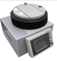
Gyro test table UPG-8
A Gyro test table checks and tests gyro instruments by longitudinal and lateral tilting, rotation and swinging. It can be used both either independently with a control panel, or as a part of AGT-8 test system.
UPG-8 gyro test table consists of three main parts:
– Control panel
– Control unit
– Turn unit
Controlling of Gyro test table carried out by the control panel with preset parameters and statuses of the unit.
Control panel interacts with control unit.
Control unit converts signals for turn unit and provides power supply of the table.
Test table has a test platform (rotating disc) for an instrument checked. The platform can change its angular position about steady horizontal base.
Software of the control panel provides a user-friendly interface, manages test procedures and displays its results.
Control panel has STOP red button that instantly stops the test platform in case of emergency.
A mount creates rotation angles about longitudinal (roll angle) and lateral (pitch angle) axes of an instrument tested. The unit consists of:
– A mount
– Adapter plates for various instruments
– Three set screws
– Four cap screws with nuts.
The mount can be used either separately or in combination with turn tables. Screws fix the instrument in a hole of the adapter plate. Two clamps on an inner ring hold the plate on the mount.
Test system AGT-4М
A complex, designed for on board of Mi-17, Mi-171, Mi-172, Mi-8, Mi-8MTV, Mi-8MT, Mi- 8AMT helicopters performs a schedule maintenance of an electrohydraulic autopilot AP-34B ser. 2 that consists of:
– Control panel 6S2.390.007-3;
– Control unit 6S2.399.000;
– Pitch and roll force-balance transducers 6S2.553.002;
– Yaw rate gyro 1209K; – roll rate gyro 1209G;
– Pitch rate gyro 1209E; – amplifier unit 1479B;
-Trim indicator IN-4 TU 1232;
– Altitude controller KB-11
The helicopter can carry a coupling unit BS-34-1, a filter unit BF-34, an IAS controller KZSP. The system tests the following parameters:
– Residual signal;
– Amplification factor;
– Slaving rate;
– Gain in KDK circuit;
– Angle gain;
– Altitude gains;
– Angular rate gains;
– WY proportional controller gain (for autopilot with coupling unit BS-34);
– Airspeed gains.
The system can replace an obsolete panel 6S2.702.007 from package PAA-34B. During the testing, system does the following:
– Forms required combinations of trial signals;
– Sends them to inputs of an item under monitoring;
– Records output signals of an item under monitoring;
– Estimates the agreement between the values measured and the conditions set up by normative documents;
– Forms a final report about a condition of an item under monitoring.
Software of AGT-4M saves the history of tests performed during schedule maintenance, prepares reports and prints them out.
The system is in the List of Special Measuring Instruments Used in the Civil Aviation (Registration Certificate No. 236-06-2011).
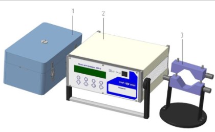
The system produced as mobile carrying control system.
System includes:
– A trunk to store and carry complex, cable assemblies and operation manual;
– A control unit; – a measuring unit;
– connecting harnesses for devices under monitoring;
– A test panel (with cable assembly) for annual inspection.
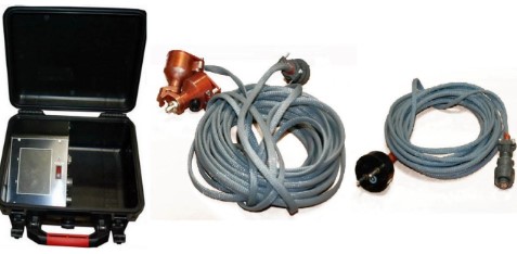
ANAXI -VIDEO vision system
Equipment offers an image of a pointer and a limb of an inlet guide vane (IGV) of TV3-117 engine. It consists of:
– Twin camera head with a connecting cable;
– Processing and displaying unit; – power harness;
– Trunk.
Twin camera head receives and transmits images of IGV limb and pointer. Processing and displaying unit holds a power unit, the controls and the indicators.
ANAXI-T-KONUS main rotor blades tracking system
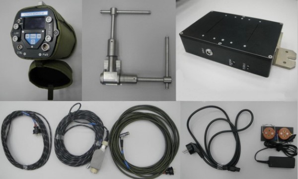
A system performs on-ground or in-flight remote measurement of blade tips positions while tracking main rotors of 2 to 8 blades. It consists of:
– Camera head unit (CHU);
– Arm;
– 220/20V power unit;
– Simulator;
– Connecting harnesses;
– SD-card;
– Cover for camera head unit;
– CD with program distributive (Russian and English interface);
– Package of operational documents;
– Trunk
CHU forms a video signal from the tips of main rotor blades, mathematically treats it, provides a real-time image of blades and coordinates, saves results of measurements. An arm holds the CHU on the helicopter and turns it on the blades.
220/20V power unit converts 220V 50-60Hz voltage into 20V DC, delivers it to a simulator, and is employed for laboratory schedule maintenance only. Simulator performs functional tests, verification and calibration (at the manufacturer facility).
The system comes in a portable version
The software of the system offers:
– User-friendly interface to manage testing procedure and display its results
– Database for testing results
– Compiling and printing-out of testing results
ANAXI-T IS THE TEST&MEASUREMENT BRAND OF ANAXI TECHNOLOGIES