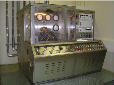
Military Aircraft Components Test Bench
ANAXI -T-SS Aircraft Components Test Bench tests all components and hydraulic systems in today’s jet or piston aircraft.
Capabilities
• Manual Control Modes
• Human/Machine Interface (HMI) displays flow, pressure, temperature, calibration, diagnostic, & warning signals
• Manual Control Panels (MCP)
• Programmable Logic Controller (PLC)
Main Hydraulic Circuit
• Two independent dynamic hydraulic test circuits, each capable of providing either:
• 25 GPM up to 3,000 PSIG OR 20 GPM up to 6,000 PSI,
• And in combination can provide 50 GPM up to 3,000 PSIG OR 40 GPM up to 6,000 PSI.
• Actuator Test Circuit: 1
• Supply and Return Ports: 4 each
• HP Supply Circuit filtration: 3-Micron Absolute
• Return Circuit filtration: 10 micron Absolute
• Two Supply Circuit flow meters: 0.1 – 50 GPM OR 0.1 to 40 GPM
• Return Circuit Back-Pressure Controls: 0 – 5,000 PSI OR 0-6,000 PSI
Low Pressure Circuit
• Low Flow: Up to 10 GPM & 250 PSI
• Supply Circuit flow meter: 0.1 – 15 GPM
• Hydrostatic Circuit Up to 10,000 PSI
• Pneumatic Circuit (GN2) Up to 6,000 PSI
• Option: P&MT Console for Pump and Motor Tests
• AND 20002 Test Pad
• High Speed Induction Motor: 250 HP, 2,000 IN-LB torque, 15,000 RPM bi-directional
• Regenerative Variable Frequency Drive: Operates and precisely controls the High Speed Motor
• Pump Test Circuit: Closed Loop, up to 70 GPM & 5,000 PSI OR 70 GPM & 6,000 PSI
• Pump Case Drain Circuit: 0 – 10 GPM
• Patch Test Capability
• Motor Test Circuit: Open Loop, up to 50 GPM & 5,000 PSI OR 40 GPM & 6,000 PSI
| ITEM | FEATURES | COMPETITION TEST BENCHES | ANAXI -T-SS |
| 1 | Advance Design | Old Technology based on 3,000 PSI Test Pressure. | New generation 6,000 PSI Hydraulic Test Bench with the latest state of the art features like Machine Human Interface (MHI) including built-in DAS on Main Hydraulic Console (MHC). |
| 2 | Human Machine Interface (HMI) | Not user friendly | The Human Machine Interface (HMI) is very user friendly, allows for human monitoring, input, and display of hydraulic fluid temperature & pressure, refrigeration temperature and pressure, ambient temperature, warning, and status indicators. All inputs from temperature and pressure sensors and HMI inputs are processed by a Programmable Logic Controller (PLC), which receives signal from temperature sensors, pressure transducers, and also from HMI inputs from MHC. |
| 3 | Programmable Logic Controller (PLC) | Competition is using custom hardware rather than standard commercially available controllers | The main tasks of the PLC are logic control, fault detection, system major faulty protective shutdown and data acquisition, including flow rates, pressures, temperatures, and condition of hydraulic oil filters. See attached ANAXI -T-SS PLC Channel List upon request. |
| 4 | Data Acquisition System (DAS) | DAS, PLC & HMI are likely located on a separate Console | DAS, PLC & HMI are located on the Main Hydraulic Console (MHC). |
| 5 | Graphic Displays | No or Limited Graphic Displays & MHC Channel Listing. | Graphic displays for parameters in form of digital data, can be displayed in HMI Screen, recorded and stored in HMI flash memory in the Excel compatible format. For parameters, see page 1/12, 2/12 and 5/12 as attached in HMI Display (MHC) upon request. |
| 6 | Test Sink Area (UUT) | Test Sink Area may be located on a separate Test Sink Area. | Test Sink Area fitted with Protective Cover is located on our MHC Console provides safety and ease of UUT Testing by Operator. |
| 7 | Inputs & Outputs | Limited Inputs & Outputs are also likely located on a separate Control Console. | All our Inputs & Outputs (1 to 126) are neatly located on our MHC Console, which offer ease of UUT Testing by Operator. See attached MHC Controls & Indicators upon request. |
| 8 | Specifications Testing & Environmental Qualifications | Built for commercial application without qualification to any stringent specification requirement testing. | ANAXI -T-SS has also been qualified to the most rigorous military requirement testing such as Environmental, Mobility, Electro Magnetic Interference, Reliability, Maintainability, Shock, Vibration, Sound Attenuation etc. as required by the US Government. |
| 9 | Production | In-production only as and when an Order is placed by Customer. | Currently with more than 80 Units in production for US Government & export market. Spares can be guaranteed for more than 20 years. |
| 10 | Gauges | Using traditional dial Gauges, which provide in-accurate readings caused by parallax reading or vibration. | No gauges, all readings are in digital numbers being displaced accurately on HMI Display Monitor. |
| 11 | Calibration | Instruments like Gauges, Temperature or Pressure Sensors, Flow Transducers etc. are required to be removed for third party annual calibration. Test Bench is out of action, time consuming and incurring annual calibration cost. | HII’s new generation design provides for calibration of these instruments at location, without requiring for their removal for annual calibration. |
| 12 | Components | Most Components are sourced from outside Vendors. | More than 90% including critical components like Flowmeters, Valves, Pressure Control Devices, Air Driven Gas Boosters or Liquid Pumps used on ANAXI -T-SS are built in‐house by our Pumps Division & Flowmetrics Inc. ensuring spares supportability for more than 20 years. |
| 13 | Instrument Verification Set (IVS) | No | Instrument Verification Set (IVS) is available to verify the acceptable accuracy of built-in Instrument like Temperature or Pressure Sensors, Flow Transducers etc. without having to remove them for annual calibration. |
| 14 | Torque Calibration | No | Torque Calibration Arm is available for calibration and associated readout of the torque transducer while it was installed on a Pump Motor Test Stand. |
| 15 | Ease of Maintenance | Troublesome and time consuming to replace Filter Elements or any consumable parts. | For example, Filter Elements or any consumable parts are easily accessible and does not require disconnecting fittings and/or interconnecting hydraulic lines. |
| 16 | Fault Diagnostic | No | If a fault exists before system operation or a fault occurs during system operation, fault conditions will immediately report to HMI message field and an audible warning horn HRN is activated. All fault conditions are permanently stored to retentive memory of HMI computer, up to 200 fault conditions |
| 17 | Life Cycle Cost | High Life Cycle Cost | Very Low Life Cycle Cost |
| 18 | Reliability Demonstration Test | No | The reliability test has been performed on the full range & capabilities of the MHC Pilot Production Unit (PPU) in accordance with MIL-HDBK-781A over 1000 hours without failures. |