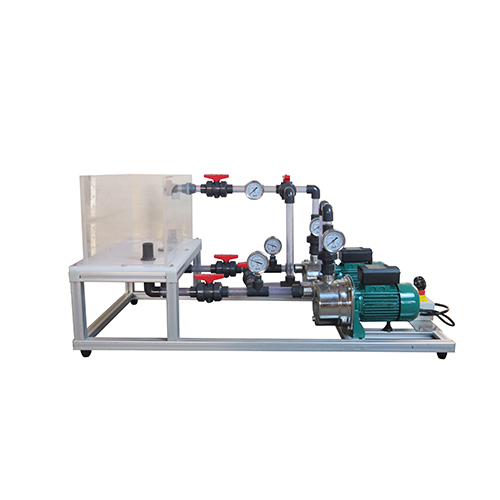
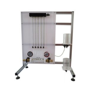
AZM7136 Series and Parallel Pumps Educational Equipment Fluid Mechanics Lab Equipment
The purpose of the experimentImproves the perceptual knowledge of the centrifugal pump and the series operating conditions and their characteristics.Draw the working curve of the single pump and the total characteristic curve of the two pumps in series.II. the experimental principleIn actual production, sometimes a single pump cannot meet the production requirements. The combination can be in series or in parallel. The discussion below is limited to the combined operation of multiple pumps of the same performance. The basic idea is that no matter how many pumps are combined, it can be regarded as a pump, so it is necessary to find the characteristic curve of the combined pump.pump parallel operationWhen a single pump cannot meet the flow required for work, two pumps or two or more pumps can be used in parallel.Qparallel=QI+QⅡ. The system characteristic curve after parallel connection is the characteristic curve of two pumps under the same head(Q-H)1 and(Q-H)2.The corresponding flow rates are added, and the corresponding combined flow rates Q after parallel are obtained, and finally (Q-H) is plotted and the curve is as shown. The two broken lines in the figure are the characteristic curves (Q-H)1 and (Q-H)1 of the two pumps, and the solid line is the total characteristic curve (Q-H) after parallel connection. According to the above, at any point M on the (Q-H) curve, the corresponding flow rate QM is the sum of the corresponding flow rates QA and QB of the two pumps having the same head, ie QM=QA+QB.
Stainless structure.
Screws, nuts, plates and all the metallic elements in stainless steel.
Diagram in the front panel with similar distribution to the elements in the real unit.
Quick connections for adaptation to feed hydraulics source.
B- TECHNICAL DATA:
Centrifugal pump: 0.37 KW, 30-80 l./min at 20.1-12.8m., single- phase,
220V/50Hz or 110V/60 Hz.
Absolute pressure manometer placed at the pump admission, range – 1 to 3bar.
2 Manometers (manometric pressure), one of them placed in the discharge and another one in the discharge accessory, range: 0 – 4 bar.
Membrane valve for flow regulating.
Two way valve: 2 positions: open or close.
Accessories:
Two flexible pipes with quick connections.
Reinforced pipe with quick connections.
Discharge accessory.
Easy and quick coupling system built-in.
Anodized aluminum structure and panels in painted steel.
Dimensions of the module: 500 x 400 x 400 mm. approx. Dimension of the discharge accessory: 500 x 400 x 250 mm. approx. Weight: 20 Kg.approx.

