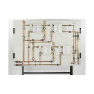
AZM2102B Solar Thermal Energy Trainer Teaching Equipment Heat Transfer Lab Equipment
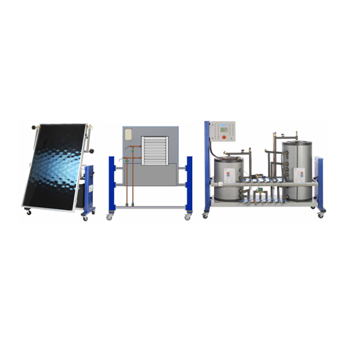
This trainer must be designed for the theoretical and practical study of solar power facilities used to obtain hot water for sanitation, air conditioning and similar services with a wide range of didactic applications.
The trainer shall be include four operating units, as follows:
MAIN MODULE
This module must be realized in a vertical frame and must contain a front panel with a real detailed hydraulic diagram of the system and the components for the circulation, storage and control of the liquid in the primary and secondary circuits.
The components must be placed vertically on a base, facilitating comfortable access to all parts for assembly and disassembly operations carried out during the practical sessions described in the handbook. The trainer must have openings on the front and backside to allow the students to see the components from each side.
The components must be the following:
Hydraulic components – Boiler support or resistance, exchanger support, solar circuit heat exchanger, magnesium anode, steel tank [capacity: 80 l, power W 1200, heating time (ΔT=45°C) h,min. 2,17, max working temperature 75°C, thermal dispersion at 65°C kWh/24h 0,96, max working pressure bar 8], solar flat collector, solar circuit loading/unloading valve, flow regulator, air release valve, safety valve, manometer, thermometer, check valve, expansion tank, flow regulator, solar circuit pump, DHW pump, pump circuit support.
Electrical components – control unit, solar circuit pump, DHW pump, pump circuit support, collector sensor hot side, collector sensor cold side, tank sensor hot side, tank sensor cold side, DHW return sensor, cold water inlet sensor, solar radiation sensor.
The front control panel must be placed in the top part of the main module and it is composed of:
- Detailed diagram of the system,
- Electronic control centre with an LCD screen for the visualization of the data,
- Power supply, protections and situation lights.
The hydraulic sockets for cold-water inlet, hot sanitary water outlet, connection to the solar panel, etc., must be located at the back of the module.
The plant must be in Ø 15 mm. copper pipe consisting of a pressing system with gaskets for solar plants.
The dimensions must be 1000 x 650 x 1650 mm.
REAL SOLAR PANEL
The real solar panel must be placed in a metal structure and connected to the main module through flexible pipes, provided with discharge, safety and filling valves.
Dimensions real collector: 1360 x 700 x 2050mm
Absorber area: 1.105 m * 1.666 m = 1.840 m2
Number of absorber pipes: 12 (MS)
Volume of the fluid: 1.5 l (MS)
SOLAR PANEL SIMULATOR
The solar panel simulator must be used in place of the real collector, in environments not exposed to solar radiation. It consists of a rapid heating boiler, complete with safety valve and vent.
Tank capacity: 5 liters
Power: 2000 W
Max pressure: 8 Bar
Dimensions collector simulator: 650 x 600 x 750 mm
CONVECTOR HEATER
As a means of applying the hot water produced, a convector heater must be available for use. It must be connected through flexible pipes.
This component must allow us to experiment with the effects of hot water obtained with this system. However, the system must be sufficiently open to permit easy use with other applications, such as hot sanitary water supply, under-floor heating, etc.
Air flow: 253 m3/h
Heating power: 2,8 kW
Water flow: 350 l/h
The trainer must incorporate six temperature probes available at six different points, and a solar irradiation sensor that will be used to calculate energy. It must be possible the connection of one heat counter at least.
The trainer must be considered as a global system for the theoretical and practical study of solar power facilities, permitting the following teaching and learning activities:
- Identification of all components and how they are associated with its operation
- Interpretation of the technical parameters of all components
- Local control of the processor
- Heating and check of the convector heater
- Forcing the reserve energy
- Forcing the recirculation pump
- Sizing criteria for ACS facilities, air conditioning, etc.
- Assembly and maintenance criteria for facilities
- Interpretation of situational data supplied by the control.
It must be complete with connecting cables, experiment manual in English language and software for data acquisition from the solar controller and processing.

