AZE3213 Conditioner for Analysis of Level, Pressure and Flow Transducers Didactic Equipment Electrical Lab Equipment
The module should enable theoritical analysis and the expireament of the following main subjects General chrastarestic of transducer; flow transducer; windmall flowmeter
Main subject of automatic control theory for linnear and countinousin -time system
types of regulator AP1D regulator (prportional-intergrative-derivative)
Response of the AP1D regulator to the typical signals
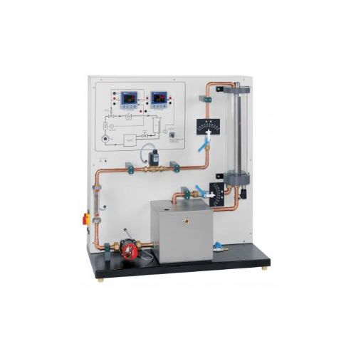
The experimental unit provides a comprehensive experimental introduction to the fundamentals of control engineering using an example of combined flow and level control. The level and flow rate can be controlled individually and as a cascade. In cascade mode the level is the primary controlled variable. The flow control then provides optimum adjustment of the controlled variable to the reference variable (setpoint).
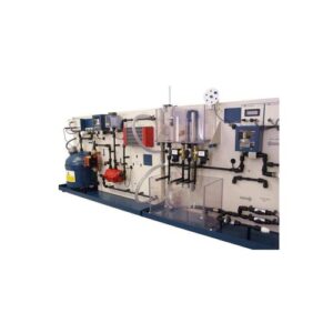
All components are clearly laid out on a vertical panel. The large-format process scheme provides an aid to understanding. A pump delivers water from a storage tank into a piping system which contains a rotameter. From there the water passes into the transparent level-controlled tank. The level is measured by a pressure sensor installed at the base of the level-controlled tank. The controllers used are two state-of-the-art digital industrial controller. The actuator in the control loop is an electromagnetic proportional valve. Ball valves in the tank outlet and in the pipe system enable defined disturbance variables to be generated. The controlled variable X and the manipulating variable Y can be tapped as analogue signals at lab jacks. This enables external recording equipment, such as a plotter or an oscilloscope, to be connected.
An instrumentation and control software with interface module (USB) is available as an accessory. This enables the key process variables to be represented, and control functions executed.
Specification
experimental unit for control engineering experiments
level and flow control individually, and cascaded
level measurement by pressure sensor
flow rate measurement by rotameter with electrical output
generation of disturbance variables by ball valves with scale
tank with overflow and scale
control valve: electromagnetic proportional valve
2 digital industrial controllers, parameterisable as P, PI or PID controllers, cascade
large process schematic on front panel
key process variables accessible as analogue signals at lab jacks
Technical data
Storage tank
stainless steel
capacity: 15L
Pump, 3-stage
power consumption: 90W
max. flow rate: 83L/min
max. head: 6m
Pressure sensor: 0…100mbar
Rotameter with electrical output: 0…600L/h
Electromagnetic proportional valve: Kvs: 1,1m3/h
2x controllers: parameterisable as P, PI or PID controller
Process variables as analogue signals: 0…10V
Connection of external recording devices (e.g. oscilloscope, line recorder) via lab jacks
230V, 50Hz, 1 phase
230V, 60Hz, 1 phase
120V, 60Hz, 1 phase
Dimensions and weight
LxWxH: 1000x500x1080mm Weight: approx. 73kg

